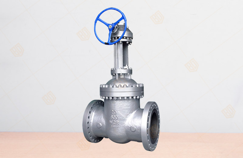
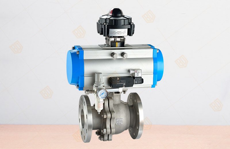
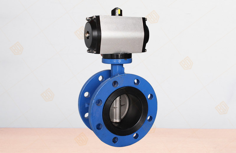
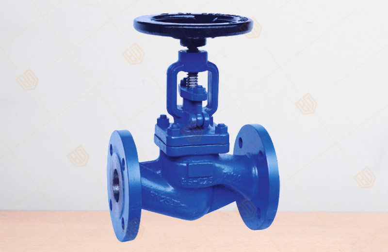
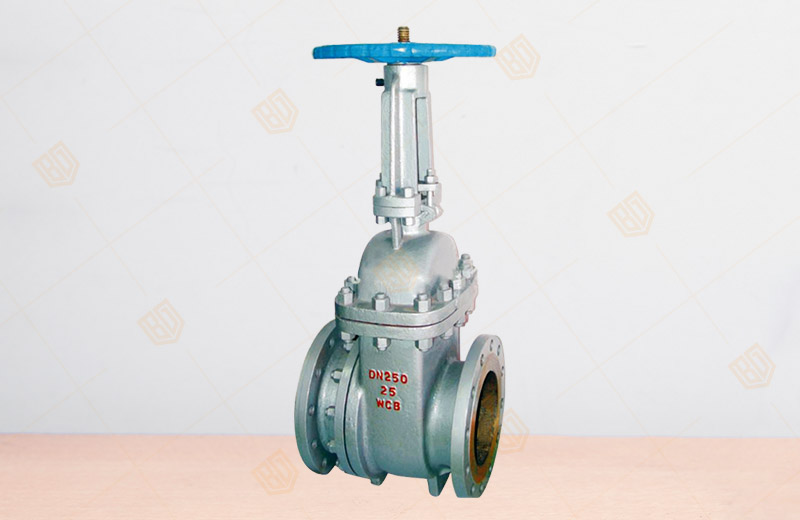
PZ41H Slag Gate Valve produced and sold by Baigang Valve Group adopts the middle flange bolt connection, and both ends of the branch pipe are flange connection or butt welding connection.Large diameter rolling bearing is set in slagging gate valve for easy opening and closing.The stem of slag discharge gate valve is treated by quenching and surface nitriding, and has good corrosion resistance, abrasion resistance and wear resistance.Slag discharge gate valve body outlet flow channel junction is reasonable, no slag, flexible opening and closing, no jam.The sealing pair of slag discharge gate valve is made of wear-resistant ceramic or wear-resistant alloy, with strong wear resistance, durable erosion resistance, abrasion resistance, small friction force and reliable sealing.The opening and closing parts of slag discharge gate valve adopt semi-sealing pair to seal with good performance.
PZ41H Slag Gate Valve summary
Flange
discharge valve is a common gate valve, the structural design is
reasonable, easy opening and closing, and has good sealing performance
and strong wear resistance, is widely used in nominal pressure PN1.6 ~
6.4MPa, operating temperature 0 ~ 100 ℃ thermal power station water
conservancy system and hydraulic system of mortar discharge system
piping, to cut off or connected to the pipeline gray water mixture, slag
water mixture.
PZ41H Slag Gate Valve Features
1, the flange slag discharge valve flange bolts in use, both ends of the branch flange connection or butt welding connection.
2, flange drain valve set large diameter rolling bearings, opening and closing easily.
3, flange drain valve body outlet flow channel junction type is reasonable, not slag, opening and closing flexible, not stuck.
4,
flange drain valve sealing material is wear-resistant ceramic or
wear-resistant alloy, wear resistance, durable erosion, scratch
resistance, friction, reliable sealing.
5, flange drain valve opening and closing parts with semi-seal pair of mandatory seal, excellent performance.
PZ41H Slag Gate Valve main parts of the material description
|
Body
|
WCB
|
|
cap
|
WCB
|
|
Bracket
|
WCB
|
|
gate
|
WCB + wear-resistant alloy
|
WCB + ceramic
|
|
Valve stem
|
2Cr13
|
|
Seat
|
WCB + wear-resistant alloy
|
WCB + ceramic
|
|
Seal ring
|
Enhance flexible graphite
|
|
filler
|
Enhance flexible graphite
|
|
Stem nut
|
ZCuA110Fe3
|
PZ41H Slag Gate Valve main shape and connection dimensions
|
PN
|
DN
|
The main dimensions and connection dimensions
|
|
L
|
D
|
D1
|
D2
|
D6
|
b
|
f
|
Zd
|
H
|
D0
|
|
1.6MPa
|
50
|
250
|
160
|
125
|
100
|
-
|
16
|
3
|
4-18
|
335
|
250
|
|
80
|
280
|
195
|
160
|
135
|
-
|
20
|
3
|
8-18
|
510
|
280
|
|
100
|
300
|
215
|
180
|
155
|
-
|
20
|
3
|
8-18
|
685
|
300
|
|
150
|
350
|
280
|
240
|
210
|
-
|
24
|
3
|
8-23
|
790
|
300
|
|
200
|
400
|
335
|
295
|
265
|
-
|
26
|
3
|
12-23
|
885
|
350
|
|
250
|
450
|
405
|
355
|
320
|
-
|
30
|
3
|
12-25
|
1015
|
400
|
|
300
|
500
|
460
|
410
|
375
|
-
|
30
|
3
|
12-25
|
1190
|
450
|
|
350
|
550
|
520
|
470
|
435
|
-
|
34
|
4
|
16-25
|
1350
|
500
|
|
400
|
600
|
580
|
525
|
485
|
-
|
36
|
4
|
16-25
|
1460
|
500
|
|
450
|
650
|
640
|
585
|
545
|
-
|
40
|
4
|
20-30
|
1620
|
550
|
|
500
|
700
|
705
|
650
|
608
|
-
|
44
|
4
|
20-34
|
1800
|
550
|
|
2.5MPa
|
50
|
250
|
160
|
125
|
100
|
-
|
20
|
3
|
4-18
|
335
|
250
|
|
80
|
280
|
195
|
160
|
135
|
-
|
22
|
3
|
8-18
|
510
|
280
|
|
100
|
300
|
230
|
190
|
160
|
-
|
24
|
3
|
8-23
|
685
|
300
|
|
150
|
350
|
300
|
250
|
218
|
-
|
30
|
3
|
8-25
|
790
|
300
|
|
200
|
400
|
360
|
310
|
278
|
-
|
34
|
3
|
12-25
|
885
|
350
|
|
250
|
450
|
425
|
370
|
332
|
-
|
36
|
3
|
12-30
|
1015
|
400
|
|
300
|
500
|
485
|
430
|
390
|
-
|
40
|
4
|
16-30
|
1190
|
450
|
|
350
|
550
|
550
|
490
|
448
|
-
|
44
|
4
|
16-34
|
1350
|
500
|
|
400
|
600
|
610
|
550
|
505
|
-
|
48
|
4
|
16-34
|
1460
|
500
|
|
450
|
650
|
660
|
600
|
555
|
-
|
50
|
4
|
20-34
|
1620
|
550
|
|
500
|
700
|
730
|
660
|
610
|
-
|
52
|
4
|
20-41
|
1800
|
550
|
|
4.0MPa
|
50
|
250
|
160
|
125
|
100
|
88
|
20
|
3
|
4-18
|
340
|
250
|
|
80
|
310
|
195
|
160
|
135
|
121
|
22
|
3
|
8-18
|
508
|
300
|
|
100
|
350
|
230
|
190
|
160
|
150
|
24
|
3
|
8-23
|
680
|
300
|
|
150
|
450
|
300
|
250
|
218
|
204
|
30
|
3
|
8-25
|
800
|
400
|
|
200
|
550
|
375
|
320
|
282
|
260
|
38
|
3
|
12-30
|
875
|
500
|
|
250
|
650
|
445
|
385
|
345
|
313
|
42
|
3
|
12-34
|
1010
|
500
|
|
300
|
750
|
510
|
450
|
408
|
364
|
46
|
4
|
16-34
|
1180
|
550
|
|
350
|
850
|
570
|
510
|
465
|
422
|
52
|
4
|
16-34
|
1145
|
600
|
|
400
|
950
|
655
|
585
|
535
|
474
|
58
|
4
|
16-41
|
1280
|
600
|
|
450
|
1050
|
680
|
610
|
560
|
524
|
60
|
4
|
20-41
|
1415
|
700
|
|
500
|
1150
|
755
|
670
|
612
|
576
|
62
|
4
|
20-48
|
1560
|
750
|
|
6.4MPa
|
50
|
250
|
175
|
135
|
105
|
-
|
26
|
3
|
4-23
|
340
|
250
|
|
80
|
310
|
210
|
170
|
140
|
-
|
30
|
3
|
8-23
|
508
|
300
|
|
100
|
350
|
250
|
200
|
168
|
-
|
32
|
3
|
8-25
|
680
|
300
|
|
150
|
450
|
340
|
280
|
240
|
-
|
38
|
3
|
8-34
|
800
|
400
|
|
200
|
550
|
405
|
345
|
300
|
-
|
44
|
3
|
12-34
|
875
|
500
|
|
250
|
650
|
470
|
400
|
352
|
-
|
48
|
3
|
12-41
|
1010
|
500
|
|
300
|
750
|
530
|
460
|
415
|
-
|
54
|
4
|
16-41
|
1180
|
550
|
|
350
|
850
|
595
|
525
|
475
|
-
|
60
|
4
|
16-41
|
1145
|
600
|
|
400
|
950
|
670
|
585
|
525
|
-
|
66
|
4
|
16-48
|
1280
|
600
|
|
450
|
1050
|
715
|
630
|
570
|
-
|
70
|
4
|
20-48
|
1415
|
700
|
|
500
|
1150
|
800
|
705
|
610
|
-
|
76
|
4
|
20-54
|
1560
|
750
|


